Pumping Tests in Bounded Aquifers
by Glenn M. Duffield, President, HydroSOLVE, Inc.
What Is A
Bounded Aquifer?
Mathematical solutions for pumping test analysis such as the well-known Theis solution typically assume unbounded aquifers of infinite lateral extent.
In reality, however, the areal extent of an aquifer may be limited by one or more boundaries. Aquifer boundaries may not impact the results of short-term pumping tests, but the effects of distant boundaries become more evident as the duration of pumping increases.
Boundaries frequently encountered in pumping test analysis include no-flow boundaries, constant-head boundaries and channel aquifers.
No-Flow (Barrier) Boundary
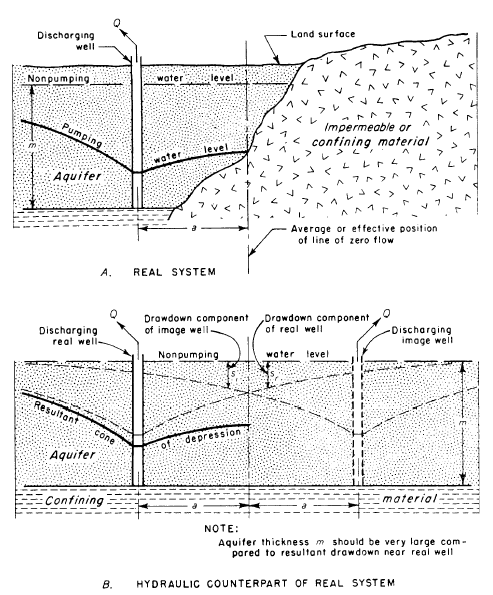
When an aquifer composed of permeable materials abuts impermeable or confining materials, it is possible to simulate the contact by a no-flow boundary. Lithologic changes (e.g., glacial outwash deposited in a low-permeability bedrock valley) or impermeable vertical faults can result in no-flow boundaries that limit the lateral extent of aquifers. No-flow boundaries are sometimes called barrier or negative boundaries.
A discharging well located near a no-flow boundary exhibits more drawdown than the same well pumping from an infinitely extensive aquifer. One may use the method of images to represent the bounded aquifer in mathematical terms by placing a discharging image well on the opposite side of the boundary from the real well (Figure 1). The image well has the same discharge rate and distance to the boundary as the real well. Thus, the drawdown at the no-flow boundary is exactly twice the drawdown observed an infinite aquifer.
Example
Consider a pumping well discharging at a constant rate, , from a nonleaky confined aquifer located at a distance from an impermeable boundary formed by an impermeable fault. To simulate the effect of the barrier on groundwater flow, position a discharging image well at a distance from the pumping well on the opposite side of the barrier.
If an observation well is located at a distance from the real well, the drawdown at the observation well is given by the Theis formula as follows:
where is transmissivity [L²/T], is storativity [-], is time since pumping began [T] and is the Theis well function [-].
Similarly, drawdown due to the image well located at a distance from the observation well is given by:
Using the principle of superposition, total drawdown at the observation well, , is simply the sum of the two preceding drawdown components:
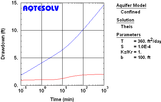
The example shown in Figure 2 illustrates two diagnostics for a single no-flow boundary. After the barrier becomes evident at 10 to 20 minutes, the semilog slope of the drawdown ultimately doubles and the magnitude of the drawdown derivative also increases by a factor of two. Prior to the influence of a boundary, look for sufficient data to estimate aquifer properties using standard methods of analysis for extensive aquifers. In Figure 2, the first derivative plateau between 0.4 and 4 minutes indicates the infinite-acting period where one could use the Cooper and Jacob (1946) method to estimate T and S.
Constant-Head (Recharge) Boundary
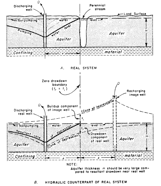
When a surface water body is hydraulically connected to an aquifer, one may represent the feature by a constant-head boundary. Lakes, streams and rivers are examples of constant-head boundaries encountered in pumping test analyses. Constant-head boundaries are alternately known as recharge or positive boundaries.
A discharging well located near a constant-head boundary experiences less drawdown than the same well pumping from an extensive aquifer. One may use the method of images to represent the bounded aquifer in mathematical terms by placing a recharging image well on the opposite side of the boundary from the real well (Figure 3). The image well has the same pumping rate and distance to the boundary as the real discharging well except that the image well recharges the aquifer. Thus, drawdown in the aquifer is exactly zero at the constant-head boundary.
Example
Consider a pumping well discharging at a constant rate, , from a nonleaky confined aquifer located at a distance from a perennial stream that fully penetrates the aquifer. To simulate the effect of the stream on groundwater flow, position a recharging image well with rate at a distance from the pumping well on the opposite side of the stream.
If an observation well is located at a distance from the real well, the drawdown at the observation well is given by the Theis formula as follows:
where is transmissivity [L²/T], is storativity [-], is time since pumping began [T] and is the Theis well function [-].
Similarly, head buildup due to the recharging image well located at a distance from the observation well is given by:
Using the principle of superposition, total drawdown at the observation well, , is simply the sum of the two preceding drawdown components:
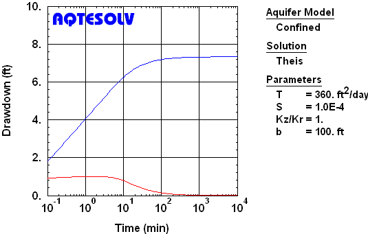
The influence of a constant-head boundary eventually produces a drawdown plateau on any plot of drawdown vs. time (linear, semilog or log-log) while the derivative during this period approaches zero (Figure 4). If sufficient drawdown data are available prior to the emergence of the plateau, one may estimate aquifer properties using standard methods of analysis for extensive aquifers.
Channel
Aquifers
Channel aquifers (also known as strip aquifers) may occur in long narrow valleys or buried channels. One may conceptualize such a channel aquifer as a permeable body between two parallel no-flow boundaries. Simulation of channel aquifer configurations requires the use of an infinite array of image wells (Figure 5).
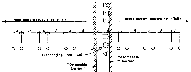
Figure 6 shows the drawdown response measured during a pumping test in a nonleaky confined buried channel aquifer near Estevan, Saskatchewan in Canada (Walton 1970). By the end of the test, each well exhibits rapidly increasing drawdown owing to the channel boundaries. Prior to the full impact of channel boundaries when the aquifer is still infinite acting, one may match the Cooper and Jacob (1946) straight-line solution to the data to determine the transmissivity and storativity of the aquifer.
 using AQTESOLV's automatic image well generation")